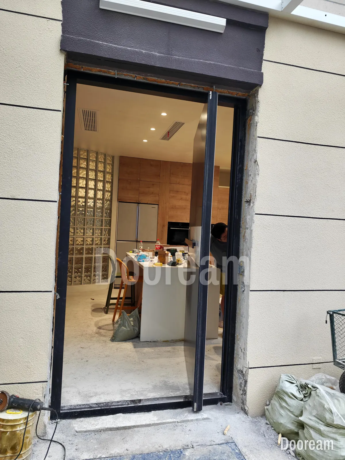
Short answer: a plan at the opening, elevations from outside and inside, vertical sections at the floor and the head, horizontal sections at the pivot side and the lock side, an enlarged pivot and floor detail, and a door schedule. Together they fix the finished opening, the pivot axis measured from the frame, the floor levels, what holds the top pivot, every gap and any cable route.
Which drawings does a pivot entrance door need?
Eight drawings and a schedule, listed below. Each answers a question the door maker would otherwise ask, or guess: where the pivot axis is, what the leaf stands on, what holds it at the top, and how big each gap is. The scales are common choices, not rules; a 4 mm gap just has to be readable.
| Drawing | Common scale | What it must show |
|---|---|---|
| Plan at the opening | 1:20 | Finished opening, frame to frame; leaf width and thickness; pivot axis from the frame and the leaf edge; side gaps; both arcs; stops; handles; nearby walls |
| Elevations, outside and inside | 1:20 | Leaf and frame sizes; each face’s design; handle, lock and reader heights; pivot axis; opening direction |
| Vertical section, floor | 1:5 or 1:2 | Floor levels on both sides from one datum; build-up; threshold; floor plate; bottom gap; drop seal; drainage |
| Vertical section, head | 1:5 or 1:2 | What the ceiling plate fixes into; frame head; top gap; top pivot; seals; cable route |
| Horizontal section, pivot side | 1:5 or 1:2 | Jamb and frame fixings; side gap; a seal that works while the leaf turns |
| Horizontal section, lock side | 1:5 or 1:2 | Stop or rebate; seals; a keep for every locking point; side gap |
| Pivot and floor detail | 1:2 or 1:1 | Floor plate; pins or recess; pivot axis from the frame; threshold junction |
| Door schedule | None | Per door: ID, sizes, leaf weight, hinge system, handing in words, floor levels, threshold, lock and power, finishes |
What should the plan at the opening show?
The plan fixes the pivot axis. Dimension it from the leaf edge, which FritsJurgens calls the pivot point, and from the frame, which the installer sets out from. FritsJurgens’ Gap Calculator defines that second figure as the pivot point plus the pivot-side gap, and works from the finished opening, frame to frame, not the structural opening.
Its worked example: a 1,000 mm opening, 60 mm leaf and 70 mm pivot point give a 984 mm leaf, 8 mm side gaps and the axis 78 mm from the frame. Open at 90°, with the axis at mid-thickness, the wide passage is about 892 mm before stops and handles. The further in the axis, the narrower it gets; check it against any clear-width rule (see measuring an entrance door opening).
Also draw:
- Both arcs: the narrow strip swings the other way.
- Single- or double-acting: FritsJurgens describes a single-acting door as held to one side by an external stop such as the frame, so draw the stop. A double-acting door needs both sides clear.
- Handles at their real projection, with the leaf open, against any return wall, cupboard or side panel.
What goes on the vertical section at the floor?
The floor section sets the leaf height and the bottom gap. Show the finished floor levels inside and outside from one datum, the build-up down to the slab, the threshold, the floor plate and its fixing, the bottom gap, the drop seal and where water drains outside.
On FritsJurgens hinges the bottom pivot sits in the leaf, so the floor takes only a plate (2026 System M+ documentation):
| Floor plate | Size | Pins | Bottom gap |
|---|---|---|---|
| Squared, on the floor | 80 × 40 × 9 mm | Two or four 8 mm, or two 30 mm for layered floors | 11 mm |
| Round, on the floor | Ø80 × 9 mm | Four 8 mm | 11 mm |
| Flush, recessed in the sill or floor | 80 × 40 × 11 mm | Four 8 mm | 7 mm |
FritsJurgens says the flush plate is the one to use with a drop seal, against draughts or on an exterior door. The leaf height is the opening height minus the top and bottom gaps. See also thresholds on uneven floors and preparing the floor for a pivot door.
What goes on the vertical section at the head?
The head section shows what keeps the door upright: a ceiling plate, or with the Top pivot Reversed the pivot itself, fixed in the head. That fixing must go into structure. FritsJurgens’ Lateral Force Calculator is blunt: a suspended ceiling is not a fixing point. Show what it is fixed to, and pass the loads to whoever checks the structure.
The weight acts away from the axis, so the two pivots take equal and opposite sideways forces. In FritsJurgens’ example, a 150 kg leaf, 1,200 × 2,400 mm, puts 325 N on each pivot with a 70 mm pivot point, or 264 N at 170 mm, and the floor carries the full 1,471 N. By the same method, a 400 kg leaf, 1,800 × 3,600 mm, with a 170 mm pivot point gives about 800 N.
FritsJurgens gives a top gap of 4–10 mm and warns: “In all situations, beware of sagging.” Ask the structural engineer how far the beam or slab over the door may deflect, and show it on the section.
What do the pivot-side and lock-side sections show?
They show the gaps, seals and stops at each edge. On a pivot door the side gaps are not a free choice: as the leaf turns, its corners need room to pass the frame, and the thicker the leaf and the closer the edge to the pivot, the bigger the gap.
FritsJurgens’ Gap Calculator works them out from the opening, leaf thickness and pivot point. Each gap includes a 2 mm tolerance; do not add it again. Check rebates, seals and projecting details through the whole swing.
- Pivot side: the edge sweeps past the frame, so the seal must work while it turns; see how pivot doors are sealed.
- Lock side: a single-acting leaf closes against a stop or rebate. Show the seal, a keep for every locking point and the fixings behind them.
How do you get power to an electric lock?
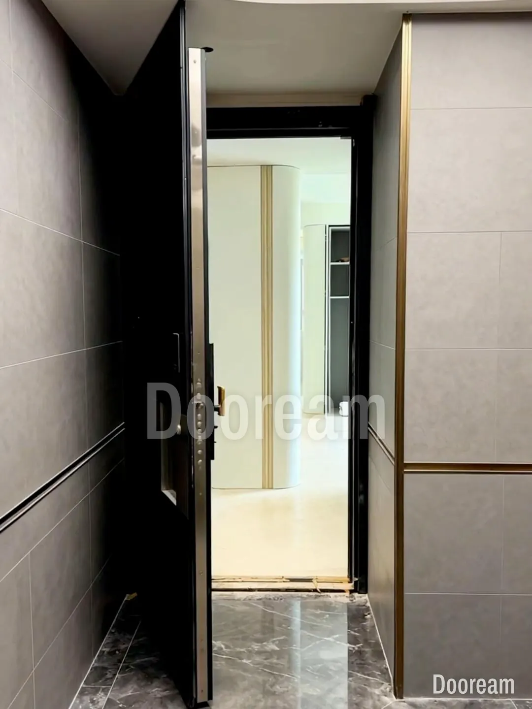
On FritsJurgens hinges the cable enters the leaf through the top pivot. Show the route on the head section: the cable entry, the conduit through the structure above, an access point and the run to the power supply. Once the head and ceiling are closed, no cable can be added.
FritsJurgens’ 2026 System M+ documentation lists a Ø7.5 mm cable entry on its Class G top pivots (pivot point fixed at 40 mm or from 70 mm) and on the Top pivot Reversed in the head jamb (from 130 mm), but not on its Class B top pivots for the lightest doors. Older documents gave a 91 mm minimum, so use the current edition, and check that the lock’s cable fits through 7.5 mm. A battery lock needs no cable; see smart locks on large and pivot doors.
Can you download CAD or BIM files for a pivot hinge?
Yes, from the hinge maker. In November 2026 the FritsJurgens System M+ page offered 2D drawings as DWG files, 3D drawings as STEP files, specification texts, technical documentation and milling and mounting manuals. Its downloads page also lists BIM as a file type, so check what exists for your system.
These files show the hardware, not your door with its build-up, face, frame, seals, lock and floor. The door maker’s shop drawing brings those together, and that is the drawing to check and approve before production; see the shop drawing approval checklist.
What should you check before issuing the door drawings for tender?
Run through this list before the set goes out. Each line is a question the door maker would otherwise send back, or answer with an assumption that you then have to find on the shop drawing. Found late, each one costs time on site.
- One door ID across all drawings and the schedule.
- Finished opening frame to frame; structural opening and fixing gap shown separately.
- Pivot axis from the frame and the leaf edge, one line from floor to head.
- Side gaps from the hinge maker’s calculator; top and bottom gaps to suit the floor plate.
- Handing in words, seen from outside; single- or double-acting; stops.
- Both arcs, the open leaf, handles, nearest walls and the clear passage.
- Floor levels from one datum; build-up, floor plate, threshold, drop seal, drainage.
- Ceiling plate fixing, loads and allowable sag, agreed with the structural engineer.
- Leaf weight and width; the hinge class depends on both.
- Lock, power and cable route, or a battery lock.
- Each face’s finish and design on its own elevation.
- Performance requirements and evidence in the specification; see the submittal checklist.
How does this work with Dooream?
We fit FritsJurgens pivots and make pivot doors up to 4,000 × 8,000 mm. The first design direction is free, usually within one working day. Then we draw the door for your opening in millimetres, converting inch drawings for you to check, with sizes, opening direction, pivot or hinge side, face, finish, hardware and lock. Production starts only after drawing approval and the deposit, and takes 35–45 days. Installation drawings come with every order; your local installers fit the door, with our remote guidance. See our page for architects or contact us.
Sources, checked November 2026: FritsJurgens, System M+ technical documentation (04/2026), Gap Calculator, Lateral Force Calculator, product catalogue 2026, System M+ downloads, downloads and technical documentation 2021.02.
Quick answers
What drawings does an architect need for a pivot door?
A plan at the opening, elevations from outside and inside, vertical sections at the floor and the head, horizontal sections at the pivot side and the lock side, an enlarged pivot and floor detail, and a door schedule. Together they fix the finished opening, the pivot axis measured from the frame, the floor levels, what holds the top pivot, every gap and any cable route.
Where can I get CAD details for a pivot door hinge?
From the hinge maker. In November 2026 the FritsJurgens System M+ page offered 2D drawings as DWG files, 3D drawings as STEP files, specification texts and technical documentation. They show the hinge, not your door, so the door maker's shop drawing still has to be checked and approved.
What should a pivot door section detail show?
At the floor, the finished floor levels on both sides from one datum, the build-up, the floor plate and its fixing, the bottom gap, threshold, drop seal and drainage. At the head, what the ceiling plate is fixed to, the top gap and any cable route. FritsJurgens gives a top gap of 4–10 mm, and a bottom gap of 11 mm, or 7 mm with a flush floor plate.